1. OVERVIEW
Scenario
In office buildings, lighting can make up 20-45% of total energy consumption [1]. As companies try to find ways to cut costs, it has become essential to find ways to upgrade lighting to a smarter solution. This can be in the form of higher efficiency light sources (such as LED), or changing the way offices operate their lighting.
Solution
By linking your office lighting to the internet through neqto, you gain access to energy-consumption control right at your fingertips. By connecting the neqto hardware to an existing lighting system, you can easily control lighting equipment with the neqto console or by using our API to create a custom app (like we did for this demo).
TECHNICAL DETAILS
Hardware Selection neqto: Components
- neqto: Bridge
Complementary Components
- FT232RL USB serial conversion module
- LM2735 DC-DC Conversion Module
- Any light controllable by PWM
- Red/Blue LED Indicators
- Push Buttons
INSTALLATION
Hardware Setup
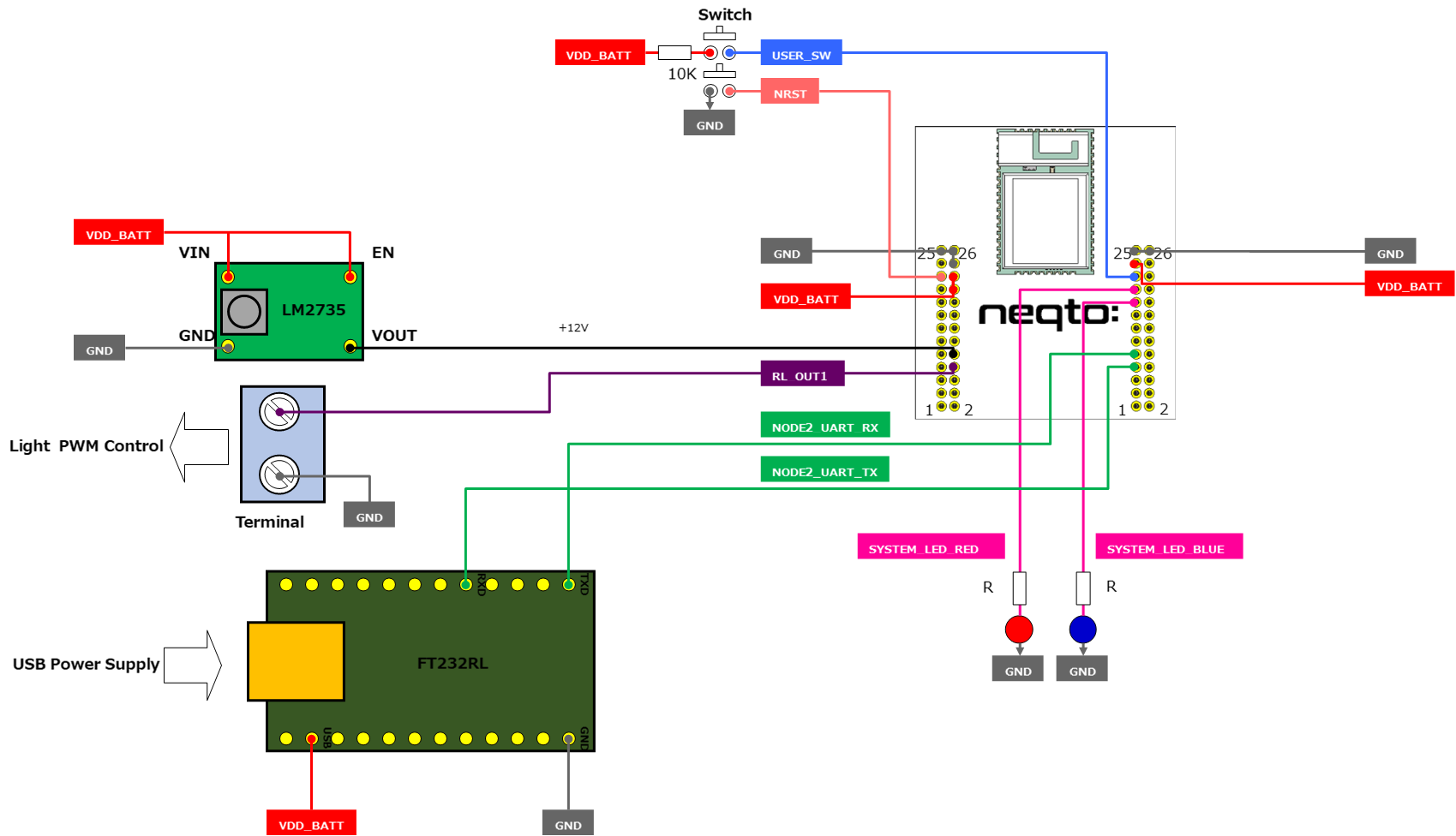
- We used the FT232RL USB serial conversion module for connecting the neqto Bridge to the serial console when required, as well as for powering it.
- A push button is required to console into the bridge and another push button was added for reset.
- LED bulbs were added to monitor the working status of the bridge.
- The light is powered using an AC adapter. The bridge is also powered by this via the FT232RL chip.
- The lights work on a control voltage of 12V, but neqto bridge works on 5V. Therefore, in order to interface between the two a MOSFET relay is required. The bridge module fortuitously has this functionality.
This allows us to control brightness of the light by controlling the voltage output of the MOSFET Relay which is controlled using PWM.
- The MOSFET relay needs to have an input of 12V. To do this, we added the LM2735 DC-DC conversion module which is similar to a step-up transformer in AC current. This module takes 5V from the FT232RL chip and provides a 12V output that is used at an input for the MOSFET Relay.
- Finally, the light control pins are connected to the MOSFET relay output and GND.
System Diagram
Software Setup
- The brightness of the light is controlled using a simple mapping of the PWM to the output voltage.
- The brightness can be a number between 0 and 100 corresponding to off and full brightness respectively.
- The light takes the command through an MQTT message which can be sent using the neqto API from the neqto Console or from a custom app that uses the API (The app created in React for this demo does just that).
nqEx.enGPIO(true);
// The GPIO port on the bridge is enabled

var lights = new GPIO(11, 9);
//A GPIO object for the lights is created with
//- the pin number (11) on which the lights are connected
//- and the PWM mode (9) as arguments

// MQTT 'push' function which is called when the bridge receives a MQTT message
nqMqtt.on('push',function(message){
  // The message should be a number between 0 and 100
  lights.setPwm(100, 100-Number(message));
});
2. CONCLUSION
Our easy-to-use application provides total control over each individual light in a system. This opens up room for endless possibilities, such as adjusting lights in a certain area based on the amount of people or daylight. By giving total remote control to the user with accessibility from anywhere in the world, customers can find drastic reductions in their energy usages, and consequently their total expenses.